There are many devices out there that store information in different ways and unfortunately, not all of them take security into account. With the advent of the Internet of Things (IoT), device manufacturers are publishing devices faster than ever, and security has become an afterthought. Your break room fridge might be running embedded Linux and your smart light bulbs that you placed within your office could be storing credentials to access your network. These credentials remain in device storage when they no longer “work” and are then discarded. Understanding the risks of these “things” is where hardware hacking comes in. Hardware hacking is the process of obtaining the flash memory from these devices and extracting it to obtain information that device engineers may or may not have secured properly.
Definitions
Universal asynchronous receiver-transmitter (UART) – The UART communicates asynchronously, which means it does not require clock or synchronization of communication. This allows for limited pin use, only requiring transmit and receive pins to be used. If the IoT device is setup with U-Boot or something similar, we can potentially modify or pull data.
JTAG – Named after the group that created it (Joint Test Action Group). It is a serial interface to allow access to a system without external access for the use of programming or debugging. The required pins are TDI, TCK, TDO and TMS.
Serial Peripheral Interface (SPI) – SPI is a synchronous serial interface. We can use them to dump flash through the use of flashrom. Required pins are Chip Select (CS), Master-In-Slave-Out (MISO), Master-Out-Slave-In (MOSI), clock(CLK).
Inter-Integrated Circuit (I2C) – I2C is a serial protocol for two-wire. It is simple and is used for low-speed peripheral devices. Required pins are Serial Data Lines (SDA) and Serial Clock Line (SCL).
Tools
Many tools can be used in hardware hacking. For our purposes, we will discuss the tools that Abricto Security leverages, albeit, this is not a full list.
-
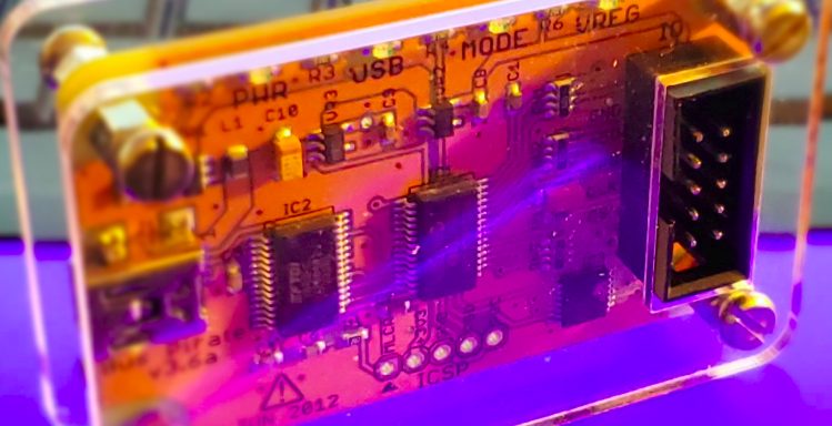
Bus Pirate: http://dangerousprototypes.com/docs/Bus_Pirate
-
The Bus Pirate is leveraged to interact with IoT devices through connections such as UART, JTAG, SPI, I2C, etc.
-
-
Flash removal tools: soldering iron, heat gun, screwdriver, etc.
-
When pulling flash through SPI flash dump, it’s sometimes required to remove the flash chip from the PCB.
-
-
Patience.
-
Working with small things will require a ton of it.
-
Other tools are used, but ultimately the tools needed will all depend on the target device that you are assessing.
Discovery
The first step of any offensive security activity is discovery and this is no different with hardware hacking. There are a few questions that must be answered before we can be successful.
How do I access the flash memory or interfaces used to configure or monitor the device?
-
Will I have to be destructive to access it?

As you can see in the example above, many IoT manufacturers put physical controls in place to make it harder for us to access the flash or interfaces that we could interact with.
-
Is there an interface on the board that we have access to?

In this example, we see that we have access to a UART interface.
-
Where is the flash and what type is it?

We see that we have a Winbond 25Q16JV.
During the discovery, it helps to also look for any other indicators that we can search for information about the board or its components. During this process, you can discover information about connections and other useful data that can be used to determine the best path forward. In this case, I discovered the user manual: https://fccid.io/TE7LBM100/Users-Manual/TE7LMB100-User-Manual-Rev-2-2950518
This gives us information about the components, interfaces and pinout of this IoT device. At this point, we also found a data sheet on the Winbond SPI flash: https://www.winbond.com/resource-files/w25q16jv%20spi%20revd%2008122016.pdf
At the end of the discovery phase, I like to list out the information that we know.
Interfaces:
- Debug UART
- I2C slave
- PWM x4
- USB2.0 for ART tool
Pinout:

Flash pin configuration:

UART Connection:
In the example above, the UART port didn’t lead to anything except a place where we could look at debugged messages. Normally within a UART port, you will find Das U-Boot, which is a universal boot loader. Depending on the version, you can interact with it and in some cases, directly dump the memory. The steps I use to do this are as follows:
- Connect to the UART interface with the Bus Pirate:

-
Dump memory with the md.b command.
-
You will need to know the memory address to start on and the size of the flash.
-

-
Copy the output to a file.
This output is not in a format where we can extract it through binwalk. However, we can make it readable for further analysis.
First, let’s run it through strings:
strings dump.txt > String.out
Now we have pulled out all the printable characters. This will give us a good start.
Next, we will convert the dump into a binary form. I like to use the uboot-mdb-dump script by gmbnomis, located here: https://github.com/gmbnomis/uboot-mdb-dump
python3 uboot_mdb_to_image.py < dump.txt > image.bin
Now that we have it in binary form, let’s use binwalk to extract any data we can (and if we’re lucky find some juicy information).
binwalk -e image.bin
Now we should have a folder with any data that could be extracted by binwalk. In my experience, this does not always work. I often find it more valuable to spend my time reviewing the strings output.
Part 2 will cover SPI flash dumps.
Thanks for reading. Subscribe to our newsletter below to be notified when we publish future blog posts.
References
http://www.interfacebus.com/Design_Connector_I2C.html
https://en.wikipedia.org/wiki/I%C2%B2C
http://dangerousprototypes.com/docs/Bus_Pirate_I/O_Pin_Descriptions
https://en.wikipedia.org/wiki/Serial_Peripheral_Interface
http://dangerousprototypes.com/blog/bus-pirate-manual/bus-pirate-spi-guide/
http://dangerousprototypes.com/docs/Bus_Pirate
https://github.com/gmbnomis/uboot-mdb-dump
https://en.wikipedia.org/wiki/JTAG
https://www.circuitbasics.com/basics-uart-communicat
